BEFORE STARTING THIS PROJECT...
If you are the maker into radio frequency communication technology or someone who is just interested in this module, you will find this project amazing for you. The Reyax RYLR896 LoRa Transceiver Module is based on LoRa technology, thus, it uses long-range communications technology with a very low power consumption. This transceiver is based on the UHF frequency band which you can change in its configuration files with a USB to Serial cable. In this project, I did not configure the modules manually and I just used them as it arrived, but, you can always configure them for your preference, with the documentation downloads provided on the Reyax website. There are many aspects of this modules which you can change such as the: bands, addresses, frequencies, bytes of information transmitted and much more. Now, before starting this project, you will need some required components which include:
- 2 Reyax RYLR896 LoRa Transceiver Module (one module as a transmitter and another as a receiver but both can be interchanged to work as either.)
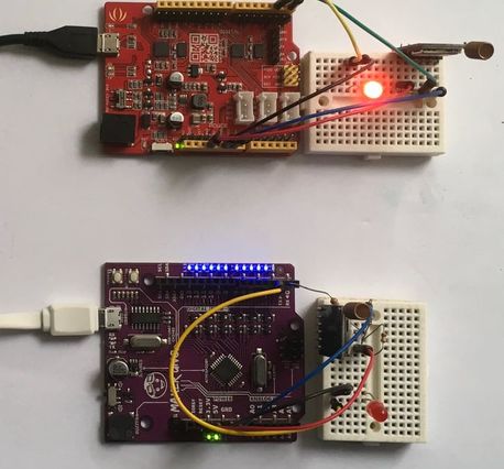
- 2 Arduinos (the Maker Uno and the Seeeduino v4.2 will be used in this example)
- 2 breadboards
- 2 USB Data Cable (depends on the Arduino)
- 9 Jumper Wires (Male to Male)
- 2 LEDs (any colour)
- 1 4.7KΩ resistor
- 3 10KΩ resistors
mounting the circuit
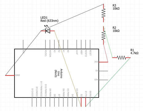
Note: The Reyax RYLR896 modules are not included in the schematics above.
|
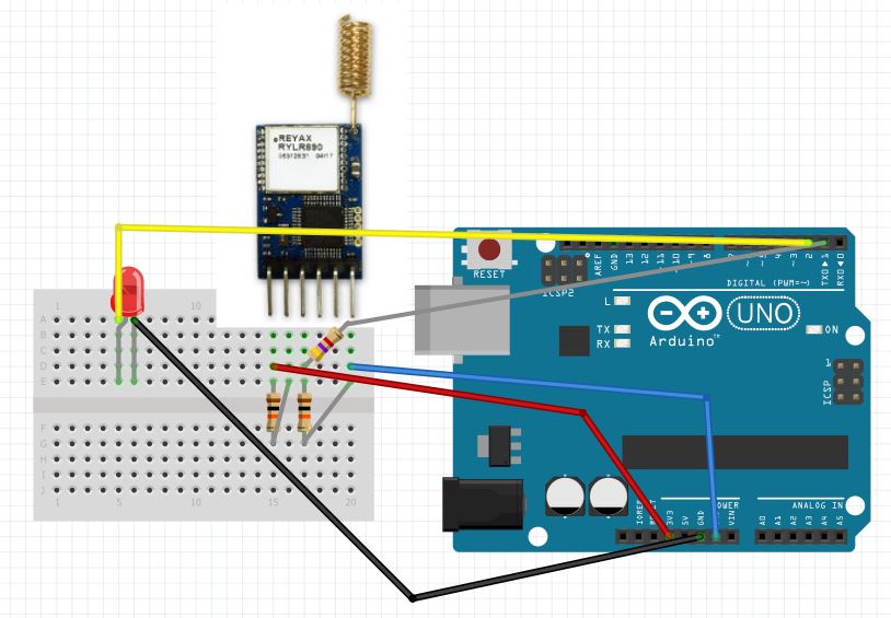
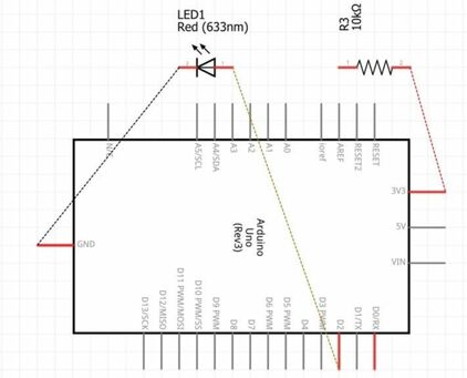
The mounting of the transmitter circuit for this project is fairly simply so let's get into it! Before starting, unplug your Arduino to avoid short circuits for the overall safety of yourself and the components. First, plug in the Reyax RYLR896 module into your breadboard, facing you, as you see in the diagram above. Secondly, insert 2 jumper wires in the breadboard to connect GND (-) on the Reyax module to any GND (-) pins on the Arduino, and the VDD (input voltage) pin on the Reyax to the 3.3v (+3.3 volts) pin on your Arduino. Next up, insert one of your 10K resistors into the breadboard, to connect the GND (-) and RXD (Data Receive) together, as seen by the diagram above. Insert another 10K resistor in your breadboard between VDD (input voltage) and NSRT (reset) on the Reyax as well. Now, use your 4.7K resistor to connect RXD (Data Receive) on the Reyax module to D1 (digital pin 1) on the Arduino directly. Furthermore, use one of your LEDs and place it into the breadboard, with its legs (cathode and anode) in two separate columns. Wrapping this whole mount up, use two jumper wires to connect the anode of the LED to D2 (digital pin 2) on your Arduino and the cathode of the LED to GND (-) on your Arduino. This finishes the mounting for the transmitter!
|
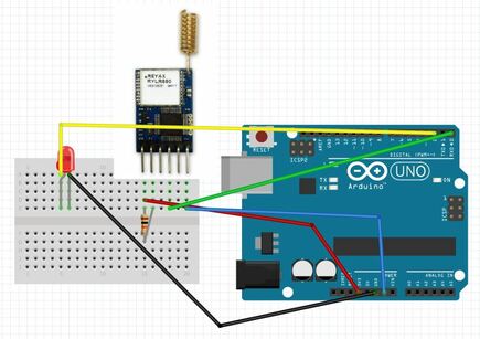
The steps to mounting the receiver side of this project are less than the transmitter steps, so let's dive right into it without further a due. Before starting, unplug your Arduino to avoid short circuits for the overall safety of yourself and the components. First, insert the Reyax RYLR896 module into your breadboard like you see in the diagram above. Secondly, use a jumper wire to connect the GND (-) pin on the Reyax module to one of your GND (-) pins on your Arduino. Then, use another jumper wire to hook up the TXD (Data Transmit) pin on the Reyax to D0 (digital pin 0) on the Arduino. After that, use yet another jumper wire to wire the VDD (input voltage) pin on the transceiver to 3.3v (+3.3 volts) on the Arduino. Now, connect your last 10K resistor to your breadboard between the 3.3v (+3.3 volts) and NRST (reset) pin of the module as shown in the diagram above. Furthermore, take an LED and insert it into your breadboard, between two columns, separating the legs. Connect the anode of the LED to D2 (digital pin 2) on your Arduino and connect the cathode to a GND (-) pin on your Arduino. Your mounting for this circuit is done!
|
the code
|
Arduino Reyax RYLR896 LoRa Transceiver Module Project Code (Transmitter)
|
Arduino Reyax RYLR896 LoRa Transceiver Module Project Code (Receiver)
|
about the code
transmitterThe code consists of a few lines, which is simple for a beginner to understand so let's go through it right away! We first define the pin, D2 (digital pin 2) which the LED is connected to. Then, in the second line, we define an extended size variable, lastTransmission, which we will use later to store some bytes of data. In the third line, we declare a read-only variable, interval, which is set to the integer, 1000. Now, we are now at the infamous void setup section, starting with declaring the baud rate for serial communication, 115200 bauds. We also set the LED pin which we have declared, as an output pin, meaning that information will be sent to that pin. The void loop is now here, starting off with an if statement, stating: if the time counted from the start is bigger than the value of the lastTransmisson + interval, then do the following. If the if statement is true, it prints a message, "AT+SEND=0,8, Testing!", and turns on the LED, waits for 100 milliseconds, turns the LED off again and sets the variable lastTransmisssion, as the value of the time counted from the beginning to be used in the loop. This whole if statement will be looped over and over again and this wraps up the explanation for this piece of code.
|
receiverSimilar to most of the codes we have in our projects on this website, this piece of code is fairly simple and beginner-friendly, so let's get through it! Similar to the code in the transmitter, we also define a pin for our LED, D2 (digital pin 2) in our first line, then we declare a variable in the form of a string, called incomingString. Now, the void setup part has arrived, with the first line declaring the baud rate for the serial communication, 115200 bauds. The second line sets the output pin of the LED, D2 (digital pin 2), so that information can be sent to that pin instead of information being sent from that pin. Now comes the void loop section which starts with an if statement stating: if serial data is available, replace the variable of incomingString with the serial strings coming in. Another if statement is also after that, which states: if the incoming string of data looks like the string, "Testing!", turn on the LED, wait for a 100 milliseconds and turn the LED off again. These two if statements will be going forever until the power of the circuit is disconnected or there is a malfunction in the circuit. The explanation is finished.
|
Make sure you check out the review for this module by clicking here.

