BEFORE STARTING THIS PROJECT...
This project involves yet another Arduino-compatible display which can be used as an output to display any information in the form of graphics, text or animations. Since this is a 1.3" 240x240 IPS (In-Plane Switching) TFT display module, it does offer a high-resolution colour display with fine graphics, and that is one of the things which I really enjoy about this display. It is also very easy to program, as it runs on the STT789 display, which is helpful to know, as the Adafruit ST7789 library supports this display, and is what we will be using today. The code used below is a fairly complex code at first, which showcases this display's capabilities and what it can do, in terms of functionality. For the wiring, a 6-pin wiring configuration is used with the SPI interface to the Arduino, which will be shown below. Finally, for this project, here are the components which you will need:
- 1 1.3" 240x240 IPS TFT Display Module
- 6 Jumper Wires (Male to Female)
- 1 Arduino (the Seeeduino v4.2 is used in this example)
- 1 USB Data Cable (depends on the Arduino)
- 1 1.3" 240x240 IPS TFT Display Module
- 6 Jumper Wires (Male to Female)
- 1 Arduino (the Seeeduino v4.2 is used in this example)
- 1 USB Data Cable (depends on the Arduino)
MOUNTING THE CIRCUIT
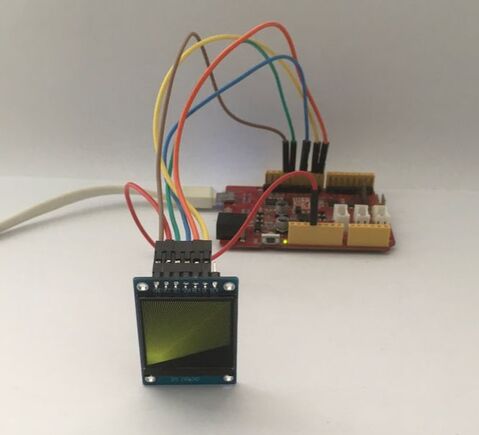
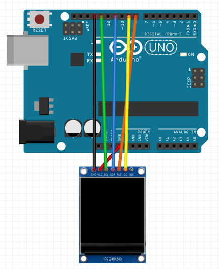
This project is fairly straightforward to set up so make sure you start by unplugging any power source feeding into your Arduino to prevent any shorts while wiring. Firstly, take a jumper wire and connect the GND pin on the display to any of your Arduino's GND pins and follow that up by connecting the VCC pin from the display to the 3v3 pin of your Arduino to supply a +3.3 volt power supply to the module. +5v will have a possibility to damage the display. Now, for the i2c connections, hook up the SCL (Serial Clock) pin of the display to A13 (analog pin 13) on the Arduino and the SDA (Serial Data) pin to A11 (analog pin 11). For the RES (Reset) pin, connect it up to A8 (analog pin 8) as well as the DC (Data/Command) pin to A9 (analog pin 9). The hardware part is finally done!
the code
Please download the code library from the link given before compiling and uploading the program: https://platformio.org/lib/show/12/Adafruit%20ST7735%20and%20ST7789%20Library
Arduino 1.3" 240x240 IPS TFT Display Module Project Code
about the code
This code may seem slightly intimidating at first, due to its length and much newer functions, but once it is broken down, it isn't so hard anymore. In the first three lines, we declare libraries for running this display, the graphics used, and for the interface used, which is the SPI interface. In the next three lines, the RST (Reset) and DC (Data/Command) pins are defined, which are connected to A8 (analog pin 8) and A9 (analog pin 9). In the next line, we initialize the Adafruit ST7789 library for use with this display and we follow that by defining the value of pi as a float variable in that next line. We will be using this float variable later on for graphics and calculations needed. The void setup section is now here where we first start by begining serial communication with a baud rate of 9600 bauds and printing a test message which is "Hello! ST7789 TFT Test!". In regards to the display, we address that our display module is of 240x240 resolution and we set the rotation of our display in the next line. If your display is flipped, remove tft.setRotation(2). From there, we print the text "Initialized" as our display is now correctly set up. After that, we count up the seconds from the startup with the millis() function and store it in an unsigned 16-bit integer, named time, for use later. We then fill up the TFT screen with a black colour. Since we already started the stopwatch which counts up, we can always reset the stopwatch back to zero by using subtracting the time function with the millis(). To end off this section, we set a delay for 500 milliseconds before moving on. This section onwards will only be for the animations, graphics and images displayed on the screen, and we start off by filling the screen with a black background and writing some text with a white colour before a 1-second delay. Proceeding that, we execute a print test which basically is already programmed to print out a set of text in different font colours and sizes. We end this test by setting a delay for 4 seconds. From this point, the rest of the code is responsible for printing out the different graphics, which can be composed of shapes, pixels and text. All the different graphics and its individual code are mentioned at the end of the code so I recommend really going through this program to learn all the commands, which can help you build your own demo code, even with your own personal images being displayed. This project is now done!


