
BEFORE STARTING THIS PROJECT...
The MLX90614 Infrared Temperature Sensor can be used as a helpful tool or just for tinkering around within the electronics hobby. This project's simplicity ensures that anybody interested in Arduino, electronics, temperature sensors or any subject, essentially, can follow this tutorial themselves. We will mainly utilise a MLX90614 Infrared Temperature Sensor to detect an object's temperature without any contact at all and to also sense the ambient temperature surrounding this sensor. The results will be displayed in both, degrees Fahrenheit and degrees Celsius on the serial monitor. Many real-world applications uses an infrared temperature sensor to either be an aid for the user or for autonomous monitoring, and some of those applications include: body thermometers, fire detectors, water heaters, room heaters etc. Now, let's get into this project, but make sure you have the following parts:
- 1 MLX90614 Infrared Temperature Sensor
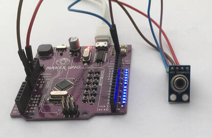
- 1 Arduino (the Maker Uno is used in this example)
- 4 Jumper Wires (Male to Female)
- 1 USB Data Cable (depends on the Arduino)
- 1 MLX90614 Infrared Temperature Sensor
- 1 Arduino (the Maker Uno is used in this example)
- 4 Jumper Wires (Male to Female)
- 1 USB Data Cable (depends on the Arduino)
mounting the circuit
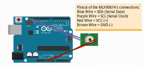
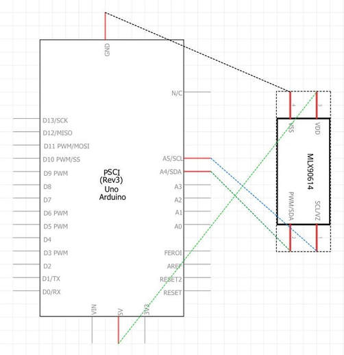
With this project requiring a simple 4-wire connection as part of this sensor's i2c interface, the mounting of this circuit should be fairly simple for new makers especially, when no breadboard is even needed. Before we start, remove any power from the Arduino or the sensor to prevent any shortage or electrical currents from running through your circuit while it is live. This is important to any connections in any of the projects we have, as it could harm the components or it could even harm you possibly. Now let's get into the wiring by first using a Male-Female jumper wire to connect the VIN (+) pin on the MLX90614 Infrared Temperature Sensor to the 5v (+) pin on your Arduino board. Secondly, use another wire to connect the GND (-) pin on the sensor to any of your GND (-) pins on your Arduino board. Now, we will connect the i2c pins, starting with connecting the SDA (Serial Data) pin on your temperature sensor to the SDA (Serial Data) pin on your Arduino board and the SCL (Serial Clock) pin on the sensor to the SCL (Serial Clock) pin on your Arduino board again. The mounting of this circuit is done!
the code
Arduino MLX90614 Infrared Temperature Sensor Project Code
about the code
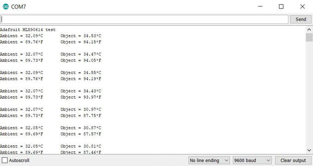
With this code consisting of basic functions, arguments and many more aspects of C++, there is nothing which can get easier than this sketch. It is based on simple commands to use this sensor in the Arduino IDE, perfect for any beginner. So, to get into it, the first two lines of this sketch declares libraries which we will use, the Wire library for our sensor's interface, and the Adafruit MLX90614, a library specifically built for reading data from the MLX90614 sensor. The third line is an instance which basically states that we will be using the MLX90614 sensor throughout this sketch. Next, we encounter the standard void setup section, where it starts with stating that the serial communication's rate will be at 9600 bauds. Then, the following command prints out a string, "Adafruit MLX90614 Test" into the serial monitor, for us to know that the code is working well. The next line begins the sensor's communication altogether. At this point, the void setup section is now done, and the void loop section is now present in this sketch. In this section, we print the string, "Ambient =", and then we print the ambient temperature in Celsius directly after that string, using the Serial.print(mlx.readAmbientTempC()); command. The next line is similar, where it prints the string, "Object = ", and then the object temperature in Celsius using a similar command to the one I have said about the ambient temperature's command. This same concept repeats itself to print the ambient and object temperature in Fahrenheit for the next consecutive two lines. This process of repeating this series of data with an interval of 500 milliseconds every time goes on forever until power is disconnected or your sensor is disconnected. Our sketch is finally wrapped up now!
Make sure you check out the review for this module by clicking here.
