before starting the project...
This project is one of my many simple projects, consisting of a light sensor mainly. The TEMT6000 ambient light sensor is an ordinary sensor which senses its surroundings like a human eye does and it is very similar to a LDR (light-dependent resistor). Essentially, the TEMT6000 can be defined as a silicon NPN epitaxial planar photo-transistor used for sensing the visible spectrum of light. This sensor can be implemented in everyday electronics such as sensing changes in backlight for phones, and controlling the backlight as well. For this project, the parts you will need include:
- 1 TEMT6000 Ambient Light Sensor
- 1 Arduino (the Keyestudio Uno is used in this example)
- 3 Jumper Wires (Male to Female)
- 1 USB Data Cable (depends on the Arduino)
- 1 TEMT6000 Ambient Light Sensor
- 1 Arduino (the Keyestudio Uno is used in this example)
- 3 Jumper Wires (Male to Female)
- 1 USB Data Cable (depends on the Arduino)
Mounting the circuit
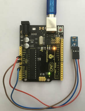
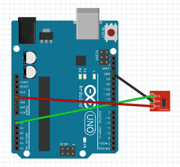
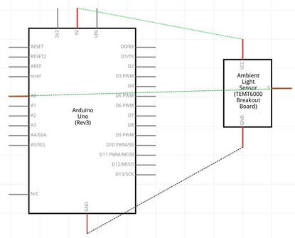
The hardware requirements are so little and the mounting of this circuit is so simple that it only took me a few seconds! Before starting, make sure you start with no power or any electrical current going through your Arduino microcontroller. You are now ready to start so first, you need to connect the signal pin on the TEMT6000 ambient light sensor to A0 (analog pin zero) on your Arduino board by using one of your jumper wires. Then, you need to connect the GND (-) pin of your sensor to any GND pins on the Arduino board, also, make sure you connect the positive (+) pin of your sensor to the 5v (+5 volts) pin on your Arduino board. The hardware part of this project is done, just three connections from the module and it's done. Please remember that your TEMT6000 sensor may come in different variations and pinouts such as mine, remember to not rely always on the pin order in the image, and make sure to look at which pins are connected to which before setting it up.
The Code
Arduino TEMT6000 Ambient Light Sensor Project Code
About the code
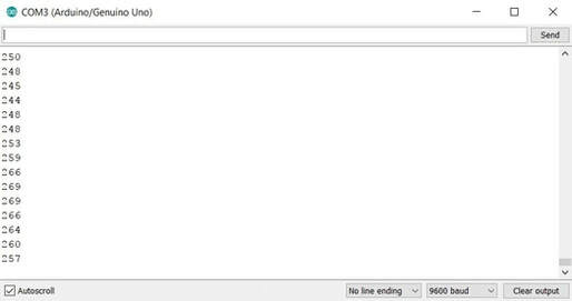
The code consists of basic commands and functions, inclusive of everything you would need to build up a basic interface with sensors. The code starts off with declaring a pin for the variable temt6000Pin, this is set to A0 (analog zero). We now get into the setup block of the program where we get ready for the serial data communication in the loop section, where we read the data coming in to the Arduino and display it on the serial monitor. Basically, the 9600 baud rate represents the bits per second for this particular pin (A0), it sets up the serial communication. Next, we move onto the loop section where another variable, value, is declared. Now, this variable is set to receive the raw readings (0 to 1023) from the sensor. Then, the percentage we have found will be printed onto the serial monitor for us to see. This data given will be printed every 200 milliseconds. That is it for this simple, but yet short piece of code!
Make sure you check out the review for this module by clicking here.


