
BEFORE STARTING THIS PROJECT...
|
|
|
|
This project will introduce you to OR logic in electronics, specifically, the OR logic gate. In the next few projects, the other parts of digital logic and its gates will be covered, but for this project the CD4011 IC will be used to simulate how an OR gate works. When any one or both of its inputs are HIGH, the output turns HIGH. But when both of its inputs are LOW, the resulting output will be LOW, so we can see here the difference between the OR gate and NAND gate, which is the fact that when both inputs are LOW with a NAND gate, the output is HIGH. For this project, we will be using two push buttons as inputs and a LED to represent the output. The components needed to make this project includes:
- 1 CD4011 NAND Gate (https://bit.ly/2o86uT3)
- 1 breadboard
- 2 10KΩ resistors
- 1 470Ω resistor
- 1 LED (any colour)
- 9 Jumper Wires (Male to Male)
- 1 9v Battery (or any other 9 volt source with jumper wires to connect to the breadboard)
- 1 9v Battery Clip (optional)
- 1 CD4011 NAND Gate (https://bit.ly/2o86uT3)
- 1 breadboard
- 2 10KΩ resistors
- 1 470Ω resistor
- 1 LED (any colour)
- 9 Jumper Wires (Male to Male)
- 1 9v Battery (or any other 9 volt source with jumper wires to connect to the breadboard)
- 1 9v Battery Clip (optional)
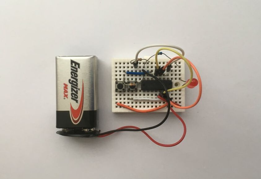
mounting the circuit
|
|
- Start by removing any power going into your breadboard to prevent any shorts with the components.
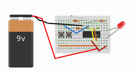
- Position the CD4011 IC into the breadboard with the first pin (marked with a circle) on the upper right side of your breadboard as seen in the picture above.
- Place your LED with its cathode (-) on the top part of the breadboard (the top section) and its anode (+) on the bottom part of the breadboard (the bottom section) as shown above.
- Use a jumper wire to connect the cathode (-) of the LED to pin 11 of the IC.
- Then use a 470Ω resistor to connect the anode (+) of the LED to pin 7 of the IC.
- Use another wire to connect pins 1 and 2 together, as well as pins 5 and 6 together.
- Link pins 3 and 13 with a jumper wire and pins 4 and 12 with another jumper wire.
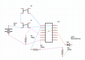
- Now place two pushbuttons next to each other as shown in the circuit diagram above.
- Connect a jumper wire from pin 14 of the IC to the bottom left leg of the first button.
- Connect another jumper wire from pin 14 of the IC to the bottom left leg of the second button.
- Use a jumper wire to connect pin 1 from the IC to the top right leg of the second button.
- Use a 10KΩ resistor to connect pin 7 from the IC to the top right leg of the second button.
- Connect a jumper wire from pin 5 from the IC to the top right leg of the first button.
- Use a 10KΩ resistor to connect pin 7 from the IC to the top right leg of the first button.
- With a 9v battery, connect the positive wire to pin 14 of the IC and the negative wire to pin 7 of the IC.
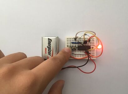
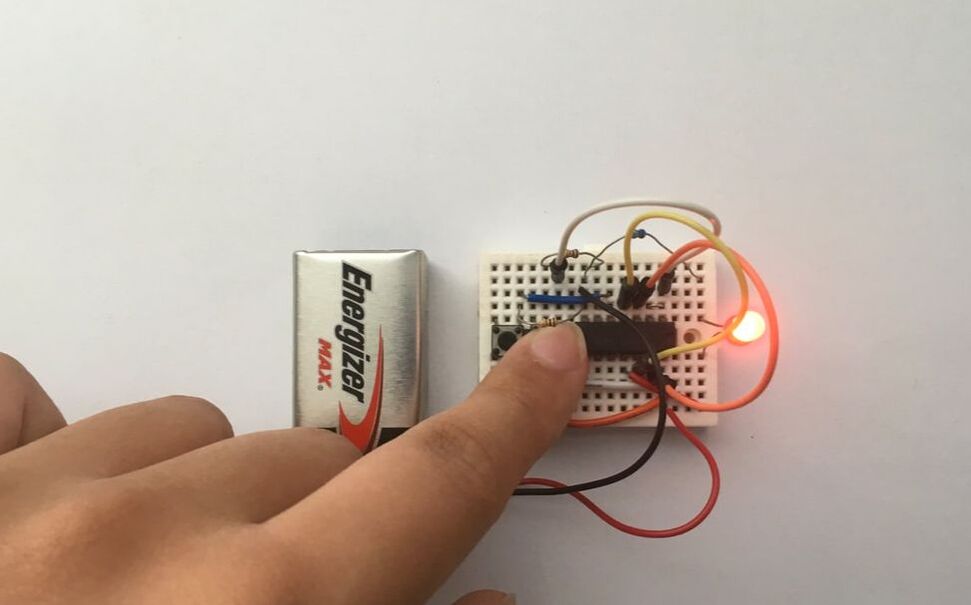
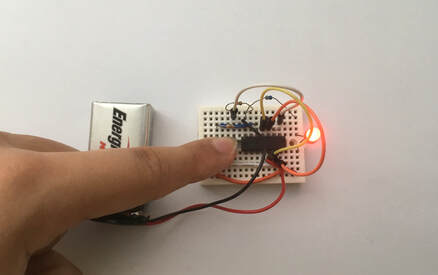
- Now, you should be able to turn on the LED from pressing either or both of the buttons.
If you need any electronic components for your projects, please feel free to purchase components from LCSC Electronics: https://lcsc.com
