
BEFORE STARTING THIS PROJECT... |
Credits go to https://urlzs.com/38drH
|
|
|
|

|
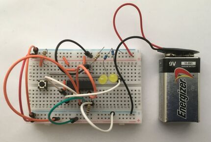
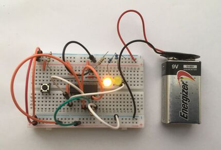
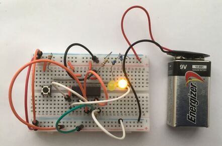
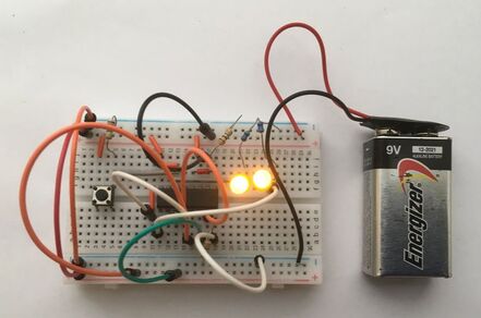
This 2-bit binary counter project marks the first General Electronic Project where it is focused on a particular IC (integrated circuit) mounted onto a breadboard. The IC which we will be using is the CD4027 CMOS Dual JK Flip Flop, which will be used to make a 2-bit binary counter, counting from figures 0 to 3 in binary form. This circuit uses two LEDs (Light Emitting Diodes) which act as visual output indicators for the binary figures. This circuit basically is composed of two T flip flops (a modified single input JK flip flop) chained together where the output of the first flip flop is connected to the input of the second flip flop. When the clock signal is low with a T flip flop, the input won't affect its output state, so the clock signal must be high for the inputs to be active. This makes a T flip flop a bistable latch where the clock signal is the control signal with two stable states based on its inputs. Also, in this circuit, the output of the first LED connects via a NOT gate (inverter) to the input of the second T flip flop. We will be using a simple push button to feed in the input signals to count up in intervals of one. The circuit diagram above shows you how the two flip flops are linked together and there is a picture above showing you the four binary sequences displayed on the two LEDS with every button press. Pictures are also above of the four binary figures displayed on the LEDs in this circuit. For this project, you will need as follows:
- 1 CD4027 CMOS Dual JK Flip Flop (https://bit.ly/2XpSCEy)
- 1 push button
- 1 breadboard
- 3 1MΩ resistors
- 2 470Ω resistors
- 2 LEDs (any colour)
- 16 Jumper Wires (Male to Male)
- 1 9v Battery (or any other 9 volt source with jumper wires to connect to the breadboard)
- 1 9v Battery Clip (Optional)
MOUNTING THE CIRCUIT
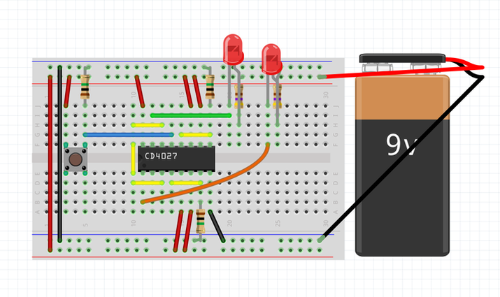
Firstly, make sure that any other components or power sources are removed from your breadboard to prevent any accidental shorts or unwanted activity from occurring. Now, place your CD4027 chip, with the first pin facing you on the centre of the breadboard on columns 11-18 as seen in the circuit diagram above. There is a little black dot indented on the chip to mark the first pin. The CD4027BE is in a 16-pin DIP package, so it will take up columns 11 to 18. Next, place a button on the centre of the breadboard with two of its legs on columns 3 and 5 on both sections of the breadboard. Make sure your button is faced the right way with a one column gap in between its two legs. Then, attach a wire from the button's top right leg to the positive power rail on your breadboard and attach a 1MΩ resistor from its top left leg to the ground power rail on your breadboard. After that, use a wire to link column 5 (top right leg of button) to column 14 (pin 13/clock 1 pin of the CD4027) and pin 16 (VDD) of the CD4027 to the positive power rail. Now, attach a wire from column 10 to pin 14/Q1 of the CD4027 on column 13 and from column 15 (pin 12/reset 1 of the chip) to column 18 (pin 9/set 1 of the chip). Also, to the left of the chip, connect a wire from column 10 of the top section of the breadboard, across the gap, to column 10 of the bottom section of the breadboard. Following that, on the bottom side of the chip, connect a wire from column 10 to column 13 (pin 3/clock 2 of the chip) and another wire from column 14 (pin 4/reset 2 of the chip) to column 17 (pin 7/set 2 of the chip). For the top section of your breadboard, connect a wire from column 11 (pin 1/Q2 of the chip) to column 23. Subsequently, connect column 15 (pin 5/K2 of the chip) and column 16 (pin 6/J2 of the chip) to the positive rail of your breadboard as well as connect another 1MΩ resistor from column 17 (pin 7/set 2 of the chip) to the ground rail of your breadboard. To wrap most of the wiring up, connect column 18 (pin 8/ VSS of the chip) to the ground rail as well. Now, back on the top section of the breadboard, connect a wire from column 12 (pin 15/Q1 of the chip) to the empty column 20 and Connect column 16 (pin 11/K1 of the chip) and column 17 (pin 10/J1 of the chip) to the positive rail. Use your last 1MΩ resistor to link column 18 (pin 9/set 1 of the chip) to the ground rail. For your LEDs, put the anode (positive side/longer leg) of a LED on column 20 and put the cathode (negative side/shorter leg) on column 21. From column 21, use a 470Ω resistor to go to the ground rail of your breadboard. For your next LED, insert its anode (positive side/longer leg) on column 24 and its cathode (negative side/shorter leg) on column 25. Insert a 470Ω resistor from column 25 to the breadboard's ground rail. To wrap things up, you will have to add wires connecting power rail to power rail for your positive and negative power. Finally, add a power supply to your breadboard power rails supplying +9 volts. Your circuit is now mounted!
If you need need any electronic components for your projects, please feel free to purchase components from LCSC Electronics: https://lcsc.com
