This is another simple PCB circuit manages to generate a stable 200 Hz square wave and triangle wave from the common 555 timer chip. What is nice about this circuit is that it only requires a few, low-cost components and the overall design is simple enough to understand by newer makers. If you didn't know already, the 555 timer already outputs a square wave which can change in frequency easily with a potentiometer, but if we want a set triangle output, specific components must be used with specific capacitance and resistance values. By the way, for this project, you will need an oscilloscope or a frequency counter to measure the output frequency and duty cycle for both the triangle and square wave outputs. You can check out JLCPCB (https://jlcpcb.com/) Before thoroughly explaining how this circuit works, here is a quick glimpse of the schematics behind this circuit:
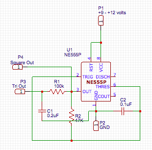
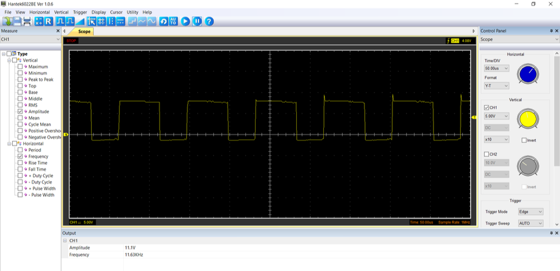
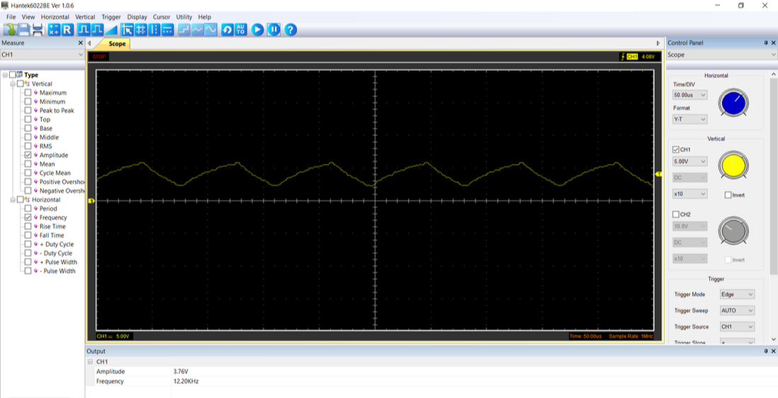
As you can see in the above schematic, this circuit simply consists of two resistors, two capacitors, the 555 timer and an input power supply of between +9 to +12 volts DC. With the 555 timer usually outputting a square wave already, the two resistors and capacitors have the function of transforming that square wave into a triangle wave. For our square wave output, the 555 timer is already configured to a 50% duty cycle astable square wave oscillator and the output of this square wave is through pin 3 of the 555 timer so when the square wave is set to a high state, C1 beings to charge via R1 therefore increasing C1's voltage gradually. Then, when the square wave switches back to its low state, C1 begins to discharge through R1, meaning that C1's voltage will gradually decrease. This charging and discharging cycle from the capacitor create a triangle wave where the rise to the peak and the fall to its trough is linear. A good tip for more waveform linearity is to increase the values of R1 and C1 to the largest value possible. With my circuit, it doesn't produce an exact 200 Hz square and triangle wave output, as seen in the pictures below, because of the fact that my components values are not the same as the ones in the schematic. The picture below shows the two outputs displayed on an oscilloscope:
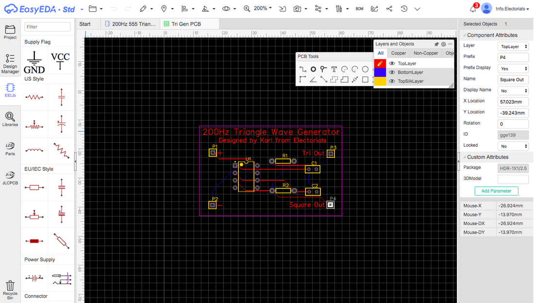
Now, that you know the basics of how this circuit works, I will also mention that with the help of JLCPCB, I managed to design my very own PCB of this circuit. By using the free, online PCB design software called EasyEDA, it took me less than an hour to draw up schematics to convert it to a PCB board to then automatically route it. Then, I simply downloaded my project's Gerber file from the EasyEDA software to upload it to JLCPCB's website. Here is what my final PCB product turned out to look like in EasyEDA:
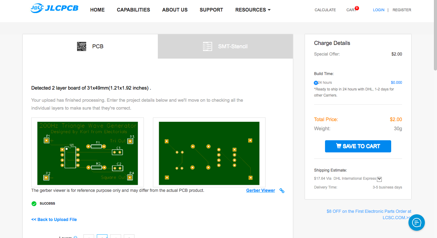
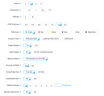
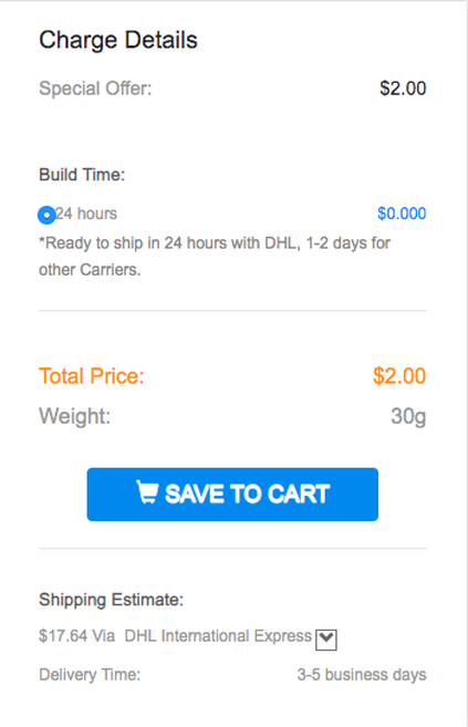
From here, I logged into my JLCPCB account, which you can do after registering with an email address and now, you can easily upload your Gerber file to your account page. From there, you can get another quick glimpse of your PCB as well as customize your PCB's colour, surface finish, thickness and other details which you wish to change. The nice feature about this page is that you will receive an instant quote on how much your order will cost and the calculated shipping fee as well. The pictures below features some aspects of this page as mentioned above:
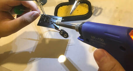
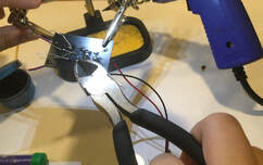
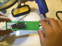
Then, you can click the "Save to cart" button, to fill in your personal payment and shipping information, which can be done in a few minutes, to eventually get your order professionally fabricated and shipped to your doorstep. I chose DHL International Express and it took less than a week for the PCBs to be shipped. Upon arrival of the PCBs, I soldered all the components to the board, clipped all of the components' legs and did a final examination of all solder joints and components with a magnifying glass. Here are pictures of what it took to finally get this circuit up and running:
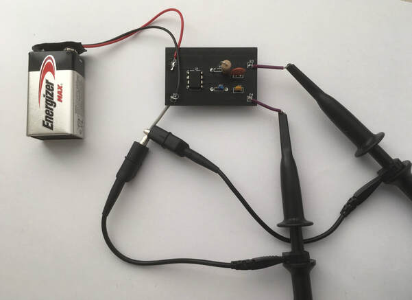
And finally, here is the final product all soldered up and cleaned well, with a 9v battery powering the whole circuit up and two oscilloscope channel probes connected to the outputs:
Go check out JLCPCB with this link: https://jlcpcb.com/

